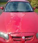
vulgalour Posted July 17, 2021 Author Share Posted July 17, 2021 Bit of pre-work tinkering and I've come unstuck, unlike the job I'm trying to complete. Should have been a simple one this, just removing the stator tube wiring. Should be a case of undoing the nut that the wiring goes through at the end of steering box, removing the olive behind, and draining the oil. Both the user manual and the online directions don't give any idea of how you drain the oil. There was no obvious drain plug. The olive was fixed very firmly in place and, since it seems to be brass, not something I wanted to apply any amount of force to in case I damaged it. After much deliberation, it was decided the best course of action was to undo the four bolts holding the end plate onto the steering box. This then released the SAE 140 oil messily as it started coming out of the top right bolt hole first and then all around the sealing edge. Allowed to drain, and expected the olive and wiring to now be free and easy to remove, or at least have enough play to slide the end plate down to see/remove any sort of retaining device. No such luck. You can get a few millimetres of play but there's a very obvious something physically stopping much movement in any direction, like there's some sort of retaining grub screw I've missed somewhere. Again, rather than force anything I've left the oil to drain and will reassemble just so we can get the car back in the garage. Without the end plate bolted on the steering wheel can't really do anything and we can't exactly leave the car sat stuck half in half out of the garage overnight. For illustrative purposes, some photographs. If anyone can see what I might have missed here, or know what else I should do, please let me know. It's going to be something obvious, I just can't see it. Dyslexic Viking, uk_senator, GrumpiusMaximus and 2 others 5 Link to comment Share on other sites More sharing options...
vulgalour Posted July 18, 2021 Author Share Posted July 18, 2021 Got some theories presented on the possible problem. The one that seems most likely is that the olive is stuck and that, in turn, is preventing everything coming out like it should. The solution is a bit of hammer time, cleverly applied, so that's a job for some point when it needs to be done. This bit can quite literally be done last if needed since it's a completely different section of the wiring that controls non-essential items (for driveway moving). GrumpiusMaximus 1 Link to comment Share on other sites More sharing options...
PhilA Posted July 18, 2021 Share Posted July 18, 2021 Looks like there's a pin through the twist of wire at the bottom? But yeah, the entire stator tube may have to be knocked out, bringing the slip ring system with it which then can be disassembled once the wheel and column shroud aren't in the way. Only a guess at how they'd assemble it. Bronze bush pressed into the steering shaft at the top, stator tube slid down through that, out through the bottom of the steering box and clamped in place there. Is there a nut that goes over the stator shaft at the bottom to secure it? Looking more closely there appears to be a pin going through the base of the steering box and the stator shaft, you may have to knock that out for it to come off. The picture isn't quite clear enough to make it out fully though. Link to comment Share on other sites More sharing options...
vulgalour Posted July 18, 2021 Author Share Posted July 18, 2021 That's not a pin, it's a trick of the light. Just went and double-checked and what you're seeing is probably an oil drop. Once you undo that nut the olive should be free and the whole lot should just slide out into the car, it's one of those "simple do this" jobs that doesn't want to. Might well be when we come back to it, whatever is jamming things has moved out of the way and it all does just slide out like it ought, you know how these jobs go. Today, rather than fiddling with the stator tube wiring, I finally figured out how to remove the interior wiring which does actually run through the headlining. It runs from the passenger semaphore, up into the roof to the interior light, across to the driver's semaphore, back up into the roof again and over the rear driver's door behind the headlining, then down the inside of the C pillar, through a gap between the rear seat and the boot, behind the trim and down to the inner wing in the lower portion of the boot. From there it branches off to the passenger side and out into the outer wing for the rear light, with the wiring running under the boot shelf. On the driver's side ther's a spur that runs off to the rear light, and another down underneath the car heading to the chassis and fuel tank sender. May have to drop the fuel tank to get to the wiring for the sender, annoyingly, since there's not a lot of space under the car and I don't think there's an access hatch for the wiring in the boot. Now got various bits of string hanging out of bits of the interior waiting for the new harness to be installed. Not the best day to choose to do the job, the inside of the roof was hot enough to feel like it might burn me, but I got it done and took as much footage as I could of the process so I can do a decent video explaining the physical route of the wiring. Because I haven't been able to find anything on the physical route the wiring takes, I'm going to make a diagram for that to help others out in the future, just as information provided by other owners has been helping us. If we'd been planning to redo the headlining the wiring would have been a lot easier to do since you'd be able to see more clearly where it goes. CreepingJesus, Twiggy, Low Horatio gearbox and 3 others 6 Link to comment Share on other sites More sharing options...
JeeExEll Posted July 18, 2021 Share Posted July 18, 2021 If you don't want to disturb the tank you could always make an access hatch for tank wiring to sender from the boot. I did this about 20 years ago with a 89 Granada. Careful measurements then use of electric jigsaw with metal blade, bit of aluminium plate (added lightness) and 4 self tapping countersunk screws. A practical 'period' mod. Documenting your findings and experience for remaining Lanchester owners is ace BTW. Low Horatio gearbox 1 Link to comment Share on other sites More sharing options...
vulgalour Posted July 18, 2021 Author Share Posted July 18, 2021 The tank is probably easier to drop than making an access hatch, in all honesty. We could also clean everything up while it's out, the whole back end of the car is covered in dried mud. JeeExEll 1 Link to comment Share on other sites More sharing options...
vulgalour Posted August 5, 2021 Author Share Posted August 5, 2021 That there is the wiring diagram as it stands for the wiring that the car came to us with. Or at least, it's the stage I'm at with laying it out. I now understand a bit better what goes where and while I'm aware that my labelling isn't conventional, I'll fix that in the next version. The purpose of this was to get my head around what the wiring was doing, and wiring in general. I'm one of those people that learns by doing more than by reading, so this was a practical exercise for me and I feel like I understand what I'm looking at a bit better now than when I started. The little open black squares are where the wiring was spliced and it's laid out pretty much as if it were in the car physically, rather than the London Underground style wiring diagrams are normally in. It should also help explain some of the confusion with the way it had been wired, what with changing colours and odd splits where they shouldn't be up front. It worked, everything did function, until things started not to. Hopefully it makes some sense to those readers with some wiring experience. Dyslexic Viking, PhilA, adw1977 and 2 others 5 Link to comment Share on other sites More sharing options...
PhilA Posted August 6, 2021 Share Posted August 6, 2021 Looking at that, does the car have two filament headlights (dip/high), or is it like Jowett and a mechanical linkage to move the reflectors? Or not at all? Link to comment Share on other sites More sharing options...
3VOM Posted August 6, 2021 Share Posted August 6, 2021 My thoughts - I'm guessing positive earth on this aged car. Are you showing any earths on the diagram? Headlights have three wires to them? Shared red to both. Blue and white to nearside. Yellow and black to offside. Red from A5 to rear lights? Can't see light switch(s). I would expect (by later standards at least) a power cable from starter to dynamo as there is nothing from the battery beyond the starter. Which in turn would feed to part or all the fuse box. Link to comment Share on other sites More sharing options...
vulgalour Posted August 6, 2021 Author Share Posted August 6, 2021 Headlights are on a floor switch, which isn't shown on the diagram, twin filament bulb rather than a moving reflector. Other items not on the diagram are the horns. The starter motor and generator/dynamo are also not shown connected because I haven't found the notes for that yet, they might have been disconnected before I made a note so that might remain a mystery. Wiring for the headlights should be an earth wire from the bulb holder to the inside of the headlight bowl, and then two extra wires from the bulb holder to the loom. However, the original wiring had been chopped and re-wrapped into the original loom, and then extra wires run along with a strange connection that was comprised of three spade connectors somehow. PhilA 1 Link to comment Share on other sites More sharing options...
3VOM Posted August 6, 2021 Share Posted August 6, 2021 https://www.dloc.org.uk/ld10 - OK not a 51. Power from starter goes to terminal on voltage regulator. Horns earth through horn switch. Floor switch might be just a dip/mainbeam switch. You got this? https://drive.google.com/file/d/1wLGPQzbXHTWxToV4XnhsEeY7ly4fgRO6/view Just found it with some more searching. What version is the voltage regulator? From the above it looks like one of those cars you get your man to grease in 27 places every fortnight. 😰 mercedade 1 Link to comment Share on other sites More sharing options...
lesapandre Posted August 6, 2021 Share Posted August 6, 2021 Lovely detailed handbook. Because a lot of these cars were intended for export it gave detailed instructions what to do - as a new owner could be in theory in the Australian outback or Malaya etc. Link to comment Share on other sites More sharing options...
vulgalour Posted August 6, 2021 Author Share Posted August 6, 2021 I've got a proper wiring diagram, and the manual, and it is indeed a car you get your man to grease regularly. These days it'll be muggins 'ere that has to do it most likely. Whatever they'd done to the wiring it did work, which is the surprising thing, I just don't really get how and why they did it the way they did when it wasn't really the easiest way to do it. lesapandre and Low Horatio gearbox 2 Link to comment Share on other sites More sharing options...
vulgalour Posted August 31, 2021 Author Share Posted August 31, 2021 Finally, it's time for a Lanchester video. The start of the rewiring job. This is going to have to be a short series because it turned into a fairly involved thing. CaptainBoom and Dyslexic Viking 2 Link to comment Share on other sites More sharing options...
Minimad5 Posted September 12, 2021 Share Posted September 12, 2021 Any updates ? Link to comment Share on other sites More sharing options...
vulgalour Posted September 12, 2021 Author Share Posted September 12, 2021 Here's a words-and-pictures update to accompany the most recent video. We are further along with the wiring job than this update suggests. Video update schedule being what it is, you'll just have to be a little patient as we work through it all. I like to have a few episodes in hand with the various projects I've got running, makes it easier to keep track of everything and makes for tidier videos. I've got a Maestro video going out on the 14th, a Sew What? video on the 21st, and Part 2 of the Lanchester's wiring adventure going out on the 28th, all being well. I'm also trying to find the time to get the Lanchester out of the garage to get the wiring a bit further along than it presently is, I had expected to have most things connected and sorted by now and would have had it not been for more fence collapse and a bit of Maestro rot to attend to. Anyway, enough waffle, here we go for those that haven't been able to check out the video for whatever reason. GrumpiusMaximus 1 Link to comment Share on other sites More sharing options...
Minimad5 Posted September 12, 2021 Share Posted September 12, 2021 9 minutes ago, vulgalour said: Here's a words-and-pictures update to accompany the most recent video. We are further along with the wiring job than this update suggests. Video update schedule being what it is, you'll just have to be a little patient as we work through it all. I like to have a few episodes in hand with the various projects I've got running, makes it easier to keep track of everything and makes for tidier videos. I've got a Maestro video going out on the 14th, a Sew What? video on the 21st, and Part 2 of the Lanchester's wiring adventure going out on the 28th, all being well. I'm also trying to find the time to get the Lanchester out of the garage to get the wiring a bit further along than it presently is, I had expected to have most things connected and sorted by now and would have had it not been for more fence collapse and a bit of Maestro rot to attend to. Anyway, enough waffle, here we go for those that haven't been able to check out the video for whatever reason. I won't lie, I prefer good old fashioned pictures 😅, so I shall wait like a good A.S member for updates. Landy Mann, vulgalour and mk2_craig 3 Link to comment Share on other sites More sharing options...
vulgalour Posted September 12, 2021 Author Share Posted September 12, 2021 Wiring part one, do check out the video above because it makes more sense of it than the words and pictures do. This is a very three dimensional sort of a job. We'd already identified that the only inoperative items on the car were the interior light and the horns. The interior light was probably dirty contacts, the horns were because they were dead so replacements were acquired that work. The decision had already been made to get a new harness which is available off the shelf from www.autosparks.co.uk to factory specification. More on that later. The trouble Pat and I were facing with the Lanchester is that the various electrical items on the car were becoming temperamental and, in some cases, totally inoperative. We knew the wiring was bad and we now had a new wiring loom to go in. What we didn't know for definite was the physical wiring route. Much of this is a one-person job, unfortunately, by its nature. I'd had more time free than Pat so I got the lion's share of all the grubby work getting the old wiring out. To give you some idea of what we're working with, here's a look at the state of play. The big knob to the left is the cowl fresh air vent, the round thing behind with the white handles is the heater box, and to the right is the steering column, this is all underneath the dashboard. A lot of the wiring uses bullet connectors for the various sections. Some are in reasonable health, many aren't, and some of the new wiring goes into old bullet connectors to join up to the old wiring. The new stuff is the plain colour, the old is the one with the neat zigzag patterning. It's not pretty. What's worse, there's been a lot of confusion for Pat and I due to a previous owner's modification to the wiring and with very little in the way of photographs to compare with what's on our car it has taken a while to figure out what's going on. When the video was recorded we had a rough idea, now that we're a lot further on in this job we have a much better idea of what's going on. What we can't make sense of is why it was done this way when there was a far simpler solution. I digress. The little white choc-bloc thing isn't original and what the wires are doing going in and out of it isn't original either. That also means that up at the voltage regulator where the two fuses for the wiring live, connections there aren't exactly as they ought to be either. This is in the engine bay on the driver's side, just above the steering column. That mass of wiring goes through the bulkhead to join up with the spaghetti in the cabin. Here you can see it draped over the steering column. Pat and I suspect this is an unfinished job and it may be that whoever started it planned to remove all of the wiring and were working through a section at a time. We'll likely never actually know. Luckily, much of our guess work is taken out by the new harness. Unluckily quite a lot of new guess work is put in because the new harness doesn't come with labelling or instructions, diagrams, or any indication of what section is for what beyond a wire colour decoder on Autosparks' website. We're told this is normal because it's OEM replacement and since this is our first venture into this sort of thing we have no experience to tell us otherwise. If we were replacing an original harness this likely would have been less of a problem, as it is it created quite a headache. We have opted to have wiring added for flasher relays and a power outlet, our only concessions to modernity. The front sidelights will become combination sidelight-indicators since there are magic bulbs that do that now, and we'll have some hidden brake and indicator lights at the back, probably in the rear window so it's at eye height for the modern driver. We'll be retaining the functionality of the semaphores and the car will look exactly as it does now, it will just be that little bit safer in modern traffic. These additions are the only labelled items on the new harness, but at least that removes a little confusion for us. After an embarrassingly long time of laying out the new harness and trying to figure out what went where I had to admit defeat. I couldn't figure out what exactly was supposed to go where physically on the car and, not knowing the actual route of the wiring, the lengths of the new harness weren't really giving me any clues. Best bet, I decided, was to just start removing the old harness and go from there, it would be easier with both harnesses side by side and if I labelled as I went confusion should be minimised. In the engine bay again, the other area of the bulkhead where the wiring pops out is on the passenger side. The lower wiring nips out alongside the washer bottle a previous owner fitted to our car, it didn't have one of those when new. Nor did it have the fuel filter. This wire I'm pointing at feeds the oil pressure sender and the coil. I had to clip off the connectors on the wires to get it through the P-clip that holds the wire and pull it through into the cabin. This is because the P-clip bolt is obscured by the fuel filter and the fuel filter is a two-person job to remove unless you've got longer arms than I have. When the filter was fitted, the fitter didn't make the nuts captive in any way and I don't have a long enough spanner or ratchet combo in the relevant size to wedge and use as a second pair of hands. Also, Pat wasn't available and I don't need the connectors on the old harness anyway since we're replacing it all. Work smarter, not harder. Next then was to figure out how to safely and carefully remove the wiring. I don't know how to draw proper wiring diagrams (yet) so I just drew what I saw as reference. This actually worked out really well for me later when making more accurate diagrams. I used what colours I saw and labelled as I went, removing one wire at a time. This then left the voltage regulator connector thingy looking a lot more empty. After pulling the wires through into the cabin that needed to go that way, and leaving the others in the engine bay, I had a colourful selection of tagged wires. I then bundled the wires together that had been together previously to keep some semblance of order to the harness to hopefully help in decyphering later. This is what you might call painstaking and I'm sure some folks would have just happily pulled everything out and thrown it away. Because Pat and I are doing this basically for the first time, we thought more caution was better, especially since we haven't a deadline to meet. "VR" for Voltage Regulator and the number to indicate which location it is on the block, 1 being at the top. The wiring diagram labels it differently to this, I did it this way so I could understand it and kept the same labelling throughout all my diagrams, at least that way my diagrams wouldn't confuse me. Back inside the cabin again (there was a lot of getting in and out of the car to do this job) I could now look for more of the wiring and see how it should be routed better. Some of the original wiring was still in place and I could see it should be secured tidily under the dashboard in more P-clips. I do show the route a bit more clearly in the video, it's difficult to capture here in static photos. I am also building a physical layout diagram for the wiring which will be freely available to help other Lanchester owners decypher the job on their cars since it was pretty much impossible to find that information when trying to do it on ours. That bit of the harness I'm pointing at above is behind the passenger glovebox, it branches off and exits the bulkhead into the engine bay again for the wiper motor. What I didn't know is that you can disconnect these wires without removing the wiper motor, but it looks like someone has had the motor off before and when it was reinstalled the wires were tucked in such a way that it wasn't clear whether or not the motor had to be removed. The motor comes out by undoing just two nuts inside the car, or in our case one nut because one was missing and looks to have been missing for quite some time. I then basically had the whole of the dashboard wiring disconnected as well as any of the wiring that went from the dashboard to the outside of the car. It was looking considerably tidier. Having the wiring out of the car highlighted how bad some of the connections really were. The old wiring is very brittle and the insulation quite fragile in a lot of places. The heater box was also removed, on our car that meant disconnecting the two water pipes in the engine bay, and undoing the three nuts. We could then disconnect the two wires and remove the whole unit. The core of the heater has failed so it needs repairing which we'll get done when we finally get the radiator done, probably at Bryans since they're local-ish and highly recommended. The interior was looking considerably tidier now. I should mention at this point I had removed the front seats which made access a lot easier and I was incredibly glad of the carpetting I'd installed, my back thanked me very much for not being jabbed by random bits of floor during some of the fiddlier bits of wire extraction. With the front of the cabin basically dealt with, I turned my attention back to the engine bay. The horn wiring was already removed, this runs up the sides of the radiator support normally to where the horns live on either side. I wanted to remove the wiring for the lights since they were the furthest items from the bulkhead and would allow me to work my way back. First of all, I had to figure out the route. Starting from the bulkhead, the wiring runs down the outside of the steering column and is usually held on with some pear shaped clamps which are long gone on our car and replaced by plastic cable ties instead. It then snakes around the steering box and into a box section that forms part of the front wing support. You can just see it looking like a brake flexi hose above the lever arm damper with the shiny bolt here. That shiny bolt is an incongruous thing too, the car came to us with that in there so we don't know if just the bolt or something else was replaced. Some of the wiring goes another route. For the headlights on the driver's side, a spur should branch off and go up into the wing support bracket and to the headlight. Another spur goes above the support bracket, through a clip, and to the sidelight unit. For the passenger side, the wiring loom runs under the radiator support bracket and repeats the wing support bracket route. However, on our car there's been some chicanery and the route is a little more complicated for the headlight wiring which goes in and out of the original harness, and alongside it, and has a weird meeting of spade connectors and a switchback. It's a mess. The route is fundamentally original, while also being overcomplicated for no good reason. The side light wiring goes up through the base of the stalk and into the bowl on the top of the wing. To access it, unscrew the screw, pop off the lens, and then twist-release the bulb holder. Once the bulb is out you can see the phenolic disc that the wiring is soldered to. In our case, new wiring has been crimp-connected to old wiring and enough solder has been used that the phenolic disc can't be removed without desoldering it. The little copper wire ring is an improvised earth which works when it feels like it, originally there's a copper or brass tang inside the base of the sidelight that does the same job, it's long since fatigued and snapped off on our car on both sides. For the headlight, pull the sprung tab on the bottom of the bezel and then prise the bezel off. We don't have a tab on the driver's side, only the passenger side, and both bezels are so tight you probably don't need the extra security of the tab anyway. This then gives you access to the wiring, in this case three bullet connectors. Two go from the harness to the bulb holder, a third serves as a ground from the bulb holder to the inside of the headlight bowl. The wiring goes through the threaded stem of the headlight and exits into the inner wing. That was as far as we got in the video, so that's where I'll end this wiring update. It's one of those jobs that takes a lot of time and leaves you with very little to show for it. As you can see from the condition of what we're starting with, the rewire is absolutely essential on this car to make it safe and, as much as possible, reliable. Scruffy Bodger, Minimad5, anonymous user and 19 others 19 3 Link to comment Share on other sites More sharing options...
Minimad5 Posted September 12, 2021 Share Posted September 12, 2021 Thanks ! No really, as I'm considering buying a loom for the P4, but wasn't sure what sort of quality etc it would be. Still think this is a brilliant looking motor. Low Horatio gearbox, vulgalour and Joey spud 3 Link to comment Share on other sites More sharing options...
vulgalour Posted September 12, 2021 Author Share Posted September 12, 2021 I really can't fault the quality of the product you get from Autosparks, it's a lovely thing and a shame to have to hide it away really. One thing to be aware of (I'll be covering it in a future update) is that the new wiring is marginally thicker than the old so on the Lanchester it was a bit of a bear to get through the guide holes in the wooden frame since it's so much tighter a fit. Because we weren't dismantling the entire car to do the wiring, we couldn't get tools in to open up the wiring route holes. It might not be a problem on the P4 since I believe they're all steel? The other issue I had is that the harness doesn't come with enough grommets of the correct size to replace all the ones the wiring goes through and I think I'll need a few extra connectors than are provided. This might just be vagaries with our car compared to a completely untouched one though, rather than any sort of fault with the Autosparks product, and Autosparks do sell all the connectors you'd likely need for a reasonable price given the apparent quality of components. Minimad5 1 Link to comment Share on other sites More sharing options...
vulgalour Posted September 27, 2021 Author Share Posted September 27, 2021 Part 2 of the wiring adventure arrives tomorrow, so watch this space for that. Pat and I haven't quite managed to find the free time to do the last of the connecting and testing, it's been a busy couple of months here, but a lot of the big time obstacles are now out of the way so hopefully we'll get a free weekend together before the weather turns to get this last little bit done. Then we can move on to the other jobs that are waiting for us like cleaning up the fuel tank, and sorting the brakes, and welding up the few holes the car has, and fitting the new engine mount, and getting the radiator repaired, and... CaptainBoom, Shite Ron, LightBulbFun and 1 other 4 Link to comment Share on other sites More sharing options...
anonymous user Posted September 27, 2021 Share Posted September 27, 2021 I was looking at what was for sale locally and this has turned up https://www.facebook.com/marketplace/item/339472274498272/?ref=facebook_story_share LightBulbFun, Shite Ron, Minimad5 and 2 others 5 Link to comment Share on other sites More sharing options...
vulgalour Posted September 27, 2021 Author Share Posted September 27, 2021 That looks a nice tidy example of a Briggs bodied car. £5k isn't unreasonable for a really clean example and the Briggs bodied cars have the advantage of being all steel, so there's no wooden frame to worry about. Low Horatio gearbox and LightBulbFun 2 Link to comment Share on other sites More sharing options...
Low Horatio gearbox Posted September 27, 2021 Share Posted September 27, 2021 That looks pretty smart and local - must resist! .....and live the lanchester dream via Vulgalour. (For now) Link to comment Share on other sites More sharing options...
vulgalour Posted September 27, 2021 Author Share Posted September 27, 2021 Resistence is futile. Get it bought Link to comment Share on other sites More sharing options...
vulgalour Posted September 28, 2021 Author Share Posted September 28, 2021 Video time. Words and pictures to follow when I get chance. Joey spud and Datsuncog 2 Link to comment Share on other sites More sharing options...
vulgalour Posted October 24, 2021 Author Share Posted October 24, 2021 Lanchester un-wiring, part 2. This is perhaps one of the dullest and most frustrating aspects of the project so far. However, it's also one of the most important jobs to do. Stripping everything down to a bare shell and chassis would undoubtedly have made this a lot easier, instead we're doing it the hard way. Picking up where we left off, here's how the headlight retaining spring works. You pull (if it's still present) a little tab under the headlight bezel and that compresses a spring which you can see in the bottom of the bowl, the two large loops there, this then allows you to easily remove the bezel and keeps the bezel in place safely the rest of the time. One of our headlights is missing the pull tab but the bezel is incredibly difficult to remove anyway so it's not a big worry, it's clearly been this way for a long time too. You've seen the headlight stripped down on the other side, this side went much the same. Sidelight this side also needed to be un-wired and as on the other side, it's missing the little tang that provides an earth and has been given one of those thick copper wire loops as a repair at some point in its life. This copper wire works most of the time, we'll be replacing it with something that will hopefully work better. The wiring runs from the sidelight to the upper side of the wing brace where there's a little clip that screws/bolts on to guide the wiring down the brace and toward the chassis. As is usual with the wiring on this car, the red and blue connectors have been out in force and one had disintegrated. Before too long I had all the wiring for the front lights pulled out to the chassis and could turn my attention to the other items branching off from the main harness, namely the wiring for the stator tube. I've never dealt with stator tubes before but I did understand the basic principle. The new harness doesn't include the stator tube wiring and I've been warned variously that it's not the nicest job to do. Since we're doing all of the other wiring on the car, the stator tube wiring will also be replaced. Someone has been here before, as evidenced by the non-factory connectors. Those connectors join the wires that run from the horn and semaphore control down the stator tube inside the steering column, to the rest of the harness. At the stator tube end, you need to disconnect it from the bottom of the steering box where the wires pop out. It's also at this moment that you realise the implications of a car with no seatbelts and a steering column that is one steel rod inside another steel rod with no ability to crumple... and then promptly put it out of your head because contemplating one's own mortality is distracting when you're trying to complete a job. At this point I didn't remove the stator tube wiring, instead I was focusing on the main harness and ancilliary items like this could be removed afterwards. Breaking the job into smaller sections like this helped me keep progressing without getting bogged down in lots of smaller challenges. Before much longer I had all of the wiring harness that served the front lights removed. In places, spectacularly poor condition. It's amazing that everything actually worked, and a little bit more clear as to why things gradually stopped working the more we dug into the car. Now I knew what was what with this, I could focus on removing the last bits of wiring from the voltage regulator connection thingy. As before, care was taken to label as I went and before long, all those wires were out too. That left me with some wires that went down to the chassis, and very little else. I tidied the wires up around one of the radiator stays (radiator is removed at present, which is why the stay is floating in mid-air) just to prevent getting into a tangle, and moved on to the next task. But first, a moment to admire the dedication someone had to keeping this wiring going. It's funny, we think of these sorts of bodges as being a terrible thing but without it, this car would not have survived as long as it did. It's a sign of someone doing their best, within their means, to keep a car going that was basically worthless and when it got too much to keep going, they squirreled it away with the intention of doing something about it later. You've got to admire that really, and then replace it for the sake of safety and reliability, of course. I decided the stator tube wiring was probably the best thing to tackle next. You're supposed to drain the steering box, then remove the nut the wiring goes through and remove the olive behind. This should then free up the stator tube which you can pull into the car and hopefully it's short enough that it doesn't actually touch the roof. I couldn't find any drain point on the steering box, only four bolts holding the end plate in place. I couldn't find any contradictory evidence and recalled watching some American hot rod builders draining steering boxes by just undoing the plate and getting the thick oil inside all over everything so assumed that must be the way it's done. Undid the bolts and sure enough, out came the really quite clean oil. Unfortunately, that's as far as I got with this one. I did discuss in various places how best to proceed because I could not get the olive to budge at all so the stator tube is stuck in the end plate of the steering box. It seems the olive has got stuck to the tube. I know a bit better now how to tackle this job then when I recorded the video so I have a few options to try, one of which is cutting a slot in the olive. Once the olive is free I should be able to pull the tube and wiring out and then repair the horn/semaphore hub that I incorrectly dismantled previously. Had to shelf this job for now. I moved on to the interior of the car, the more old wiring that could be removed the better. Easiest item was likely to be the interior light. The cover twists off, being held in bayonet bulb fashion, and you can then see the screws that hold it to the plywood square that's fastened to the wooden roof beam behind the head lining. Really simple to remove, simple unscrew the few screws holding it in place, and remove the two wires. This part of the wiring at least looked untouched. Set the interior light assembly aside for cleaning and safe keeping since there's nothing else to be done there at this point. You can also see the original salmony-pink colour of the headlining here, a much brighter colour than expected. Pat and I will be having a go at carefully cleaning the headlining since it's not as brittle as feared, but it's unlikely it will come back the same pinkish hue because so much of it will just be sun and age faded now. The semaphores need a service and the easiest way to inspect and service those would be to remove them, so let's do that. First thing I learn is that the fabric I thought had been cut through hadn't, it's actually like that from the factory. What's missing is the passenger side B pillar trim which we'll likely have to make from scratch. Pat and I have been on the look out for some replacement old brown Rexine and suitable wool to get as close as match to the rest of the interior as we can. If need be we'll use new materials, but old and aged would be better. The semaphores are held in place by two screws, one at the top and one at the bottom. These are pretty easy to access once you've removed the b-pillar trim which is also held in with two screws. One our car, the semaphores don't match, and neither do any of the fixings, and it's very clear someone has been in here before. What's less clear is exactly what was and wasn't changed. The slot on the passenger side semaphore (the newer, more orange looking one) is a very peculiar shape. The wiring is simple to remove. The top fixing screw holds two black wires, and then there's a red wire that goes to a bullet connector holder. Here's the passenger side semaphore removed. They pull into the inside of the car, you can't remove them from the outside. On the driver's side, the two black wires end in nothing but stubby little bare wires. What's really strange here is that this semphore worked just fine, the wires must have been resting in just the right place to make contact. The fixing screws on this side were also mismatched, and the bottom one had an enormous stack of washers to get it to the right place. The semaphore itself works just fine, the way it was attached and the wiring leave something to be desired. With both semaphores removed you can see the difference between them. It's not just the colour, the design of them is slightly different so that the stainless strip and lens aren't interchangable. Pat and I assume the passenger side one was replaced at some point, and we'll leave them be for as long as they work, there seems no point forking out large sums of money for matching replacements, at least for this car. With the semphores and interior light removed, it was time to figure out how to remove the wiring that goes to them. Up until the point of recording, there had been no clear answer on the physical wiring route. Similar models from a similar time period had offered suggestions, it was now time to find out what the answer really was. We had initially thought the wiring for the semaphores and interior light would go either over the front doors and down to the engine bay, or down the A pillar and join the wiring along the chassis. Instead, it turns out it takes a different route, our first clue being the wiring harness that disappeared from the boot and into a cavity alongside the rear seat on the driver's side of the car. Some careful investigation revealed that, sure enough, the wiring doubles back when it gets to the boot so that it can come back into the car. Carefully prying back the trim board that looks like the last section of the headlining showed us just where the main harness was running. Knowing this we could apply some logic to work out where it went. It was obvious it was going up over the rear door frame so it was unlikely it was going to go back across the rear seat. Also, we'd had the rear seat base out and knew there was nowhere for the wiring to actually go there that we couldn't see. This started to make sense of why the trim over the driver's side doors was loose and broken at the b-pillar; someone must have been investigating the wiring on this side. With that trim removed and set aside, the passenger side trim was also removed since we now knew that we'd need access and more proof that the wiring had been investigated was found because some of the headlining tacks were missing entirely over the B-pillar, just the rusty witness marks remained. Now it was a case of figuring out how to un-wire this. Because we weren't removing the headlining, and because we now discovered it wasn't held by bows but was instead tacked to the wooden beams of the roof, we had to work in what space was offered. Thankfully the fabric wasn't that brittle so tolerated being handled and moved out of the way quite well with no horrible tearing noises. We learned that the wiring runs up from the top of the semaphore, through a hole in the wooden frame diagonally backwards to another hole in the metal frame which then guides the wiring across the roof above the headlining. Needed more access so some more tacks needed to come out. Rather than a specialised tack removal tool, which had a habit of slipping off the tack heads and jabbing into the fabric, I used a combination of wire snips and a sharp screwdriver to pry out the tacks. This worked really very well and the headlining survived unscathed. This gave better access to get my hands and arms into the tight working space and start unthreading the wiring. on the driver's side, it's a little harder to unthread things because there's more wires going through the holes, this is because this side serves both the sempahore and the wiring for the interior light and other semaphore. Above the passenger side B pillar there's only need for the one set of wiring since it's only going to one item. While investigating the wiring route it became clear the wiring for the interior light wasn't loose. This is because it's stapled to the plywood block the interior light screws into. There's one staple on the same side the interior light fastens to, and another on the edge of the plywood. Removing these is tricky and I did have to cut the wiring hole larger to get to the staples, which are particularly nasty looking things. Then it was a case of tying string to every wiring end before pulling the wiring through. In theory, this will help guide the new wiring through the same route and make the process of re-wiring things a lot easier since so much of it is working blind because the headlining is not being removed. With care, the wiring was pulled out and into the boot. This is much easier with two people. If you're doing it on your own, whenever you feel things getting tight, check things haven't got snagged. The last thing you want is the string snapping when the wiring is in an inaccessible spot. The wiring was then held in place by the boot hinge and trim panel, and the connectors at the boot floor. I was surprisingly exhausted at this point, never underestimate the ability for this sort of job to knacker you out, especially when it's hot and you're working in a black car in the sunshine. Lots and lots of water was drunk that day, and ice creams had. Still, it felt a good milestone to reach. Next up, the boot light. I'm not really sure what's going on with the wiring for the boot light, it's clearly been messed about with over the years. I just wanted to remove the lamp for now and the wiring I could get to, later I would remove the boot lid to do a more thorough job, as will become clear in a later update. First, unscrew the inside-out-bolt (threads are on the inside of the shank) and then lift the chrome cover free, and then the glass cover. It's pretty grimey inside. There's two connectors here, one the bullet connector type as is common on this car, and the other a spade connector. The wiring is unsurprisingly terrible but the unit itself is in good shape. If the worst came to the worst, these Lucas light units are still readily available, but it shouldn't come to that. Not much else I could do there, so I moved to the only other bit of wiring that was on the top side of the car, which is the wiring for the rear lights. The rear lights had been working when we got the car and then one day they just didn't any more. We hadn't looked into it further because we knew the wiring was getting replaced, now perhaps we'd find out a reason. Rear lights are fairly easy to remove, first unscrew the big chrome screws that hold the bezel and glass lens in place. Do be careful with the lens, they really are glass. Behind that is the metal reflector, such as it is, and a rubber seal. I removed the rubber seal here because I couldn't see the fixings for the reflector, I suspect that's not always necessary. There should be one screw at the top and another at the bottom, on our car of the four screws that should hold both rear reflectors on, only one remains, the other three having snapped off in the aluminium housings that the reflectors screw to, so that's going to be fun to sort out. Predictably there was quite a bit of aluminium corrosion, dirt, and other corrosion back here. There is a rudimentary splash guard inside the rear arch that's supposed to protect this but it doesn't really. The contacts are supposed to be protected by a rubber boot which keeps the dirt out, but not the corrosion. There's nothing else to offer protection for the earth wire. Everything was covered in dirt, I can't imagine the connection was particularly good and that's probably why the lights stopped working. another thing that probably doesn't help is the wires are connected with a spring-loaded connector, much like you'd have for speaker cables on old hi-fi equipment. One connector was jammed, the other moved after a little effort. You push the exposed ends of the connector down and then you can pull the wire out, simple stuff. More evidence of wiring fettling before us is in the form of the rear lights themselves. Passenger side has what looks to be factory white reflector, with a ribbed lens. Driver's side has had the reflector repainted in red oxide, and has a later built-in-reflector type lens. Pat and I think the ribbed lens is original because the car has aftermarket reflectors screw to the boot lid. We also suspect that one of the original lenses was broken when the rear wing was hit in the distant past. Quite why only one lens was replaced even though a matching pair of the reflector types came with the car we don't know, perhaps a job that was just never got around to. That all sorted, it was time to pull out the wiring. Simply pull the wiring inside the boot once you've disconnected the rear light and through it comes, no bother. The rusty hole in the inner arch is one of the very few bits of bodywork that needs addressing and should be a nice simple repair. The bullet connectors on the driver's side were also disconnected, ready for the next bit. Last bit of wiring to get out of the boot is the bit that joins the two rear lights together. This runs along the blind side of the beam that supports the boot shelf. The boot shelf is there to keep your luggage and other things off the spare wheel and tools. The wiring is held in place with flathead bolts and nuts, with the nut on the blind side. Initially I thought the screw was into a threaded section of the support bar, but it's not. Be careful here because the bolt heads are very soft. I put a 10mm spanner on the nut and turned it back and forth a few times to break the hold, and then unscrewed the bolt from the front which seemed to work best. You can then release the P clips and remove the wiring. And that is where we leave this update because that's the end of the video. Part 3 comes out on Tuesday the 26th of October, and we shall pick the story up then. Coprolalia, somewhatfoolish, LightBulbFun and 22 others 25 Link to comment Share on other sites More sharing options...
vulgalour Posted October 25, 2021 Author Share Posted October 25, 2021 Well, I made a little mistake above. I have been made aware that what I've done there is do a write up for both part 2 of the wiring, and the as-yet-unreleased part 3 and put them all together as one post. The peril of being distracted part way through writing a post there. Oh well, it just means you get to see what's coming in the next video and I don't need to worry about writing it up later. Shite Ron 1 Link to comment Share on other sites More sharing options...
PhilA Posted October 25, 2021 Share Posted October 25, 2021 I would hedge a bet on the three-rib lens being original, friend's 1947 Humber used the same lens except in clear glass, with a different lamp holder (twin bulb, one had a red glass dome over it with a 21/5 bulb and the other a 21 for the reverse lamp). The inside of the lamp holder was painted that off-white. Phil vulgalour and Matty 2 Link to comment Share on other sites More sharing options...
beko1987 Posted October 25, 2021 Share Posted October 25, 2021 Crikey the state of that wiring! It's going to be amazing with the new loom in 👍 It's like stripping down old pre ww2 acuum cleaners, always amazing they ran at all. Old Hoover cleaners get bonus death points though as the main loom runs under where the main carry handle of the cleaner is. Pick it up whilst plugged in and nudge the perished loom and zzap! (on an entirely metal vacuum) vulgalour and lesapandre 1 1 Link to comment Share on other sites More sharing options...


Recommended Posts
Create an account or sign in to comment
You need to be a member in order to leave a comment
Create an account
Sign up for a new account in our community. It's easy!
Register a new accountSign in
Already have an account? Sign in here.
Sign In Now