


JimH
-
Posts
2,233 -
Joined
-
Last visited
-
Days Won
5
Reputation Activity
-

 JimH got a reaction from Ghosty in Korean Cortina - MOT day
That made me smile
Notice thread title that probably relates to a Hyundai Stellar Open thread, see that it indeed relates to a Hyundai Stellar Smile at the idea that back in the day a number of people commented that they looked very like a Maser Biturbo. Notice that the thread is over four years old and is very long. Jump to last page Fail to understand the relevance of a photograph of an inlet manifold from a V8. Twig that this Stellar not only looks a bit like a Biturbo but probably has about the same amount of power.
I like it when people do daft things well.
-
 JimH got a reaction from drum in It is just so Super (Sentinel).
A quick update. There are times when a lot gets done but there isn't a lot of visible progress.
However, this is reasonably visible. First fit of the front axle beam hanging on by the skin of its teeth. This is meant to be held in with a slice of 1/2" plate and 4 off 3/4" whit bolts. There will also be a 1" packing piece between the axle mount and the spring. This was to lift the chassis up to increase clearance when they converted them from solids to pneumatics. This will do for starters.
You should start to get an idea of how the front axle works. Badly, mainly.
Can't see the join. The bend is so it fits around the boiler. These were forged originally so they looked a little rough and ready. We've tried to replicate this. Once the paint is on it you wouldn't tell the difference.
So now the beam is in place we can go back to these bits which have lain on the floor for a few months while other things were done. A swivel. You see the big hole in the axle beam? That takes the pivot pin. Then the stub axles go through the big hole in the swivel. Ovbiously there are a few bronze bushes needed too.
The other thing that has been started is the cab. The footplate was cut and fitted a few weeks back so now we are happy with the curve on that all the other bits of the front apron copy it. This is the 1" angle that takes the bottom of the apron plate. Bending angle is a right pain in the arse and it takes a lot of heating and tweaking to get it right. Actually, bending angle is a piece of proverbial if you have bending rolls that can take angle but we don't so we have to freehand it.
A bit of 1" angle. Wow.
See the 12 foot radius on the front section? Important bit that. It's what makes a Super look like a Super.
The next bit is trickier. The angle sets the shape at the bottom of the cab but at the top where the roof is there is the ash bend. This was originally bent from a 3"x1" section of ash which was steamed and bent to shape. This wasn't very durable and if you look at period photographs (and a fair few current ones) you'll see ash bends bodged back together with plate, chewing gum and string. When we did the last one we fabricated the ash bend in steel which is somewhat more long lasting even if it is a bit of a pain to build.
There is a length of 1" box section at the top and the same at the bottom. There is then 3"x 1/8th flat section on the vertical faces. Tack it all together, make it look pretty and no one would ever tell the difference. Easy to say, takes a bit longer to do. It is made easier because you are trying to replicate the curves and angles of the footplate which means you have a handy, very stiff and just at the right height jig to work from. You should be able to make out the top and bottom box sections and the front vertical being tacked into place. I was actually in the process of taking it off at this point which is why there are almost no clamps on it. You never have enough clamps. Please be a tiny bit impressed with the shape. We're pretty pleased with that.
And the same from the other side. It got bigger than this after the picture was taken because it extends to the rear of the cab.
Check out the curves on that. There is a lot of welding, grinding and fettling to go before it looks plausible. Good start, though.
Things to think about while you are working. Express is falling out of favour, BTW.
We now have a Sentinel drawing for a van body which looks pretty good and shouldn't be too horrific to buy the wood for so it's definitely having a big box body on it. By the way - look at the top picture (photocopied out of a sales brochure which explains the flowery language) see the rail running around the roof of the cab? That's the ash bend. This picture isn't a perfect representation of what they actually made but it is a very good image to keep you on track while you try to work out what goes where.
Drawings from the archives. Most of the information is in there as long as you take everything with a pinch of salt.
This, for example is the rear hub for the pnuematic converstion. Make two of these and you've nearly got a back axle. Doddle. Ish.
Finally today the stiffening plate for the rear drawbar. A chunk of 1/4" plate which will be held in with 23 5/8" rivets. The bits of channel are what the water tank will hang from.
What's next:
Cab uprights to get bent
Front footplate to cut around steering box
Boiler to drop in
Front axle to get on with
Ash bend to finish
Wood cutting list to finalise
-
 JimH got a reaction from Burnside in Korean Cortina - MOT day
That made me smile
Notice thread title that probably relates to a Hyundai Stellar Open thread, see that it indeed relates to a Hyundai Stellar Smile at the idea that back in the day a number of people commented that they looked very like a Maser Biturbo. Notice that the thread is over four years old and is very long. Jump to last page Fail to understand the relevance of a photograph of an inlet manifold from a V8. Twig that this Stellar not only looks a bit like a Biturbo but probably has about the same amount of power.
I like it when people do daft things well.
-
 JimH got a reaction from loserone in Korean Cortina - MOT day
That made me smile
Notice thread title that probably relates to a Hyundai Stellar Open thread, see that it indeed relates to a Hyundai Stellar Smile at the idea that back in the day a number of people commented that they looked very like a Maser Biturbo. Notice that the thread is over four years old and is very long. Jump to last page Fail to understand the relevance of a photograph of an inlet manifold from a V8. Twig that this Stellar not only looks a bit like a Biturbo but probably has about the same amount of power.
I like it when people do daft things well.
-
 JimH got a reaction from mat_the_cat in Korean Cortina - MOT day
That made me smile
Notice thread title that probably relates to a Hyundai Stellar Open thread, see that it indeed relates to a Hyundai Stellar Smile at the idea that back in the day a number of people commented that they looked very like a Maser Biturbo. Notice that the thread is over four years old and is very long. Jump to last page Fail to understand the relevance of a photograph of an inlet manifold from a V8. Twig that this Stellar not only looks a bit like a Biturbo but probably has about the same amount of power.
I like it when people do daft things well.
-
 JimH got a reaction from LightBulbFun in Korean Cortina - MOT day
That made me smile
Notice thread title that probably relates to a Hyundai Stellar Open thread, see that it indeed relates to a Hyundai Stellar Smile at the idea that back in the day a number of people commented that they looked very like a Maser Biturbo. Notice that the thread is over four years old and is very long. Jump to last page Fail to understand the relevance of a photograph of an inlet manifold from a V8. Twig that this Stellar not only looks a bit like a Biturbo but probably has about the same amount of power.
I like it when people do daft things well.
-
 JimH got a reaction from Lacquer Peel in Korean Cortina - MOT day
That made me smile
Notice thread title that probably relates to a Hyundai Stellar Open thread, see that it indeed relates to a Hyundai Stellar Smile at the idea that back in the day a number of people commented that they looked very like a Maser Biturbo. Notice that the thread is over four years old and is very long. Jump to last page Fail to understand the relevance of a photograph of an inlet manifold from a V8. Twig that this Stellar not only looks a bit like a Biturbo but probably has about the same amount of power.
I like it when people do daft things well.
-
 JimH got a reaction from coalnotdole in It is just so Super (Sentinel).
A quick update. There are times when a lot gets done but there isn't a lot of visible progress.
However, this is reasonably visible. First fit of the front axle beam hanging on by the skin of its teeth. This is meant to be held in with a slice of 1/2" plate and 4 off 3/4" whit bolts. There will also be a 1" packing piece between the axle mount and the spring. This was to lift the chassis up to increase clearance when they converted them from solids to pneumatics. This will do for starters.
You should start to get an idea of how the front axle works. Badly, mainly.
Can't see the join. The bend is so it fits around the boiler. These were forged originally so they looked a little rough and ready. We've tried to replicate this. Once the paint is on it you wouldn't tell the difference.
So now the beam is in place we can go back to these bits which have lain on the floor for a few months while other things were done. A swivel. You see the big hole in the axle beam? That takes the pivot pin. Then the stub axles go through the big hole in the swivel. Ovbiously there are a few bronze bushes needed too.
The other thing that has been started is the cab. The footplate was cut and fitted a few weeks back so now we are happy with the curve on that all the other bits of the front apron copy it. This is the 1" angle that takes the bottom of the apron plate. Bending angle is a right pain in the arse and it takes a lot of heating and tweaking to get it right. Actually, bending angle is a piece of proverbial if you have bending rolls that can take angle but we don't so we have to freehand it.
A bit of 1" angle. Wow.
See the 12 foot radius on the front section? Important bit that. It's what makes a Super look like a Super.
The next bit is trickier. The angle sets the shape at the bottom of the cab but at the top where the roof is there is the ash bend. This was originally bent from a 3"x1" section of ash which was steamed and bent to shape. This wasn't very durable and if you look at period photographs (and a fair few current ones) you'll see ash bends bodged back together with plate, chewing gum and string. When we did the last one we fabricated the ash bend in steel which is somewhat more long lasting even if it is a bit of a pain to build.
There is a length of 1" box section at the top and the same at the bottom. There is then 3"x 1/8th flat section on the vertical faces. Tack it all together, make it look pretty and no one would ever tell the difference. Easy to say, takes a bit longer to do. It is made easier because you are trying to replicate the curves and angles of the footplate which means you have a handy, very stiff and just at the right height jig to work from. You should be able to make out the top and bottom box sections and the front vertical being tacked into place. I was actually in the process of taking it off at this point which is why there are almost no clamps on it. You never have enough clamps. Please be a tiny bit impressed with the shape. We're pretty pleased with that.
And the same from the other side. It got bigger than this after the picture was taken because it extends to the rear of the cab.
Check out the curves on that. There is a lot of welding, grinding and fettling to go before it looks plausible. Good start, though.
Things to think about while you are working. Express is falling out of favour, BTW.
We now have a Sentinel drawing for a van body which looks pretty good and shouldn't be too horrific to buy the wood for so it's definitely having a big box body on it. By the way - look at the top picture (photocopied out of a sales brochure which explains the flowery language) see the rail running around the roof of the cab? That's the ash bend. This picture isn't a perfect representation of what they actually made but it is a very good image to keep you on track while you try to work out what goes where.
Drawings from the archives. Most of the information is in there as long as you take everything with a pinch of salt.
This, for example is the rear hub for the pnuematic converstion. Make two of these and you've nearly got a back axle. Doddle. Ish.
Finally today the stiffening plate for the rear drawbar. A chunk of 1/4" plate which will be held in with 23 5/8" rivets. The bits of channel are what the water tank will hang from.
What's next:
Cab uprights to get bent
Front footplate to cut around steering box
Boiler to drop in
Front axle to get on with
Ash bend to finish
Wood cutting list to finalise
-
JimH got a reaction from drum in It is just so Super (Sentinel).
There is a load of stuff to do today and a rapidly looming deadline so let's have an update. That will put food on the table.
So the chassis is bolted together, the holes reamed and the rivets in the bag. Now all we need to do is heat them up, pop them in and job done but first you need a rivet gun. This is a McDonald gun made in Glasgow and these things have built a lot of ships. This was last used when we put a new tube sheet of the Fowler roller back in 1985 when we had two ex-riveters to help us out (YCRTA two ex-riveters to actually do the difficult bit) but now we were on our own.
There were five of us this time. Someone on the gun, one with the hydraulic holder, one on the pump, one heating rivets and one running with the white hot rivet. I got to play at being a manly proper man and work the gun. I got to do that because of my in depth knowledge and understanding of rivetted joints. Ha ha ha. We only had to put 30 5/8" rivets in. We all had the impression of long departed riveting gangs looking down on us from above pissing themselves laughing at our pitiful efforts. After a bit of arsing around I reckon we got there.
This is the front one. That keeps some bolts in it because it needs to be removed to get the boiler out.
It is hot, bloody noisy and not exactly easy work. It is no wonder that people who did this for a living were worked to death by their forties.
With the frame bashed together the next bit is the footplate which is made in two halves so you can get the boiler out. If you look back you'll see a picture of a pile of bits of plate. The footplate is made of admiralty pattern chequer plate which has diamonds rolled into it which hasn't been available for a long tie now so you have to take what you can get. We were very lucky to get a load out of an old mill and then we spent an irritating Saturday playing jigsaws with tape measures and french chalk trying to work out the best way of joining the plates in a way that minimised the number of joins and hid them as far as possible. After a full a frank exchange on views on the subject of how to do it we came up with something that made the best of a bad job.
Then it needs tacked together, turned over and marked out as per the drawing. There are a few curves that take a while to get right. Also, because you only have one go at this you do get a bit checky. Once you are happy, cebtre dab all the cut lines and break out the NM250 oxy-propane cutting torch and off you go. Then you lay into it with big angle grinders and you end up with something with lines and curves all over the place.
In the picture below you can see two short join lines on the front plate - these will be hidden by the boiler. You should be able to make out the join down the middle of the rear plate. This is annoying but hey ho. The join that runs from side to side across the hole is meant to be there. That gets bolted up.
Note how the lines of the front plate match the lines of the rear plate. It took a lot of cutting and grinding to make that happen. This is the somewhere near finished plate lifted up into position on the chassis. The cut on the hole looks scruffy because it hasn't been tidied up yet - we are working close to the S4 and we are waiting for a couple of welding screens to arrive to keep the sparks off the finished one.
This is an important bit because that set of curves across the front kind of define a Super Sentinel.
The big hole is what the boiler sits in. As you have probably worked out by now the boiler does tend to dominate the cab. And makes it very hot in there.
The axle beam waiting for the jig to be finished.
Fairly stout weld needed to hold it together.
A somewhere near finished steering box bell crank. The big straight arm hangs down and connects to the drag link.
The start of the track rod ends. These have bronze spherical seats which provide movement. There is a fair bit of machining left to do on these to make them look convincing.
The bronze seats have small springs behind them to keep enough load on things to keep them together. These are those small springs. This is very cack handed engineering. Nice springs, though.
One for the woodworkers in the audience. I found this photo of the spring hanger and slipper plates. A dovetail joint in half inch steel plate.
Drive sprockets on the carriers. This is the rear face of them. The bronze rings are a modification. When these were made the used a super crude mechanical seal on the main bearing housing which wouldn't hold small coal so we ditched them and went for a design of modern lip seal like an oil seal on a car hub. Once the carriers are on no one will see any difference. The little sprocket you see fixed to the one on the left is the drive sprocket for the dynamo. The original set up was appalling and because we tend to drive at night a lot we need something that works. This layout allows us to run a much bigger sprocket and get more speed out of the dynamo without it looking awful. Once the carrier is on the drive chain should hide almost everything.
Steam engines need a lot of oil both in the crankcase and the top end. This is the start of the mechanical lubricator that pumps something that looks like treacle into the steam supply to keep the cyliders oiled. It is driven by the engine.
A pile of boiler bits. These are the hinges that take the grates and the ash pan. They look like crude bits of tat because they are crude bits of tat.
And this finally arrived from Aus. This is the body for the valve that controls the boiler feed pump. The water pump runs all the time that the engine is running so when you don't want water in the boiler you have a bypass - sorry, in old speak - bye-pass valve that sends the flow back to the water tank. This is worked from a lever in the cab. This is a right fiddly thingwith internal ports and it had to be cast. Making a pattern for this was waaaaay beyond what we could do so we had someone quote to make one for us. Let us just say that we were glad that a nice man in Aus had already had a pattern made and got us one cast at the same time. This was very, very much cheaper. There is a lot of machining to make this thing into a finished item.
It the background you will see a shiny thing with a sphere on the end. This is the start of the other bit of the track rod ends.
Next jobs:
Carry on with front axle
Get some stock bar to start building up the front of the cab
Work out what wood is needs to make a start on the cab
-
 JimH got a reaction from 808 Estate in It is just so Super (Sentinel).
I'll put this here because it is hardly worth a new thread and I didn't see one on tin bashing. One of the longer term projects is a Merryweather steam fire engine which has been in the family for a fair few decades now. This is in need of, among other things, a new boiler. Oddly the one task which was putting a mental block on proceeding with the design and documentation of a new boiler was the cladding. The cladding? Surely such a trivial thing as insulation would be a doddle compared with manufacturing a new boiler.
Aye well this has bothered us for many years decades because the cladding is entirely brass and that age hardens and cracks. The chemicals in polishes doesn't help this process (apparently). The upshot is that after 110 years or so the cladding looked like this. Notice all of the cracks? One option was to have it heat treated and start silver soldering up the cracks. Then a more skilled basher than I could sit there with a soft faced slapper gently dressing out the ripples and dents.
Here's a thing. When researching the availability of panel beating tools don't type "leather faced slapper" into Google and expect anything useful back. Ho hum.
Anyway. The problem with this job is that rather simple looking radius at the top. You need to lose metal to fold it in which is tricky. An option is to spin it. This was no good because it was too deep for all of the spinners we spoke to. We could have made it in two sections with a band round the middle but that is hardly pretty. Hell, they managed in 100 years ago so we can't let it beat us. Again, maybe a better basher could have sat down with hammer and dolly and just keep dressing it down until they got there. I suspect this is the approach taken originally. The offending curve and the offensive cracks.
So where to begin? First buy a big sheet of brass, roll it into a cylinder and silver solder the butt joint. So far so easy. Then, taking the largest sledgehammer to crack a nut you acquire some slabs of polypropylene from a plate heat exchanger and bolt them into a large plastic block. Then you put it in your big lathe and turn the curve on it. This was done by calculation. Yes kids, maths in action!
This is the plastic guide mounted on a big piece of pipe the right distance from the ground.
Then all you need to do is anneal the brass, slipin onto your guide and off you go with your hammers. The results speak for themselves.
Shite. This sorry mess is what we keep hidden behind a bench after it was cut off. Luckily we made the cylinder much longer than it needed to be. We reckoned we had another four attempts before another sheet of brass was needed. After some thought and discussion we came up with the idea of crimping the top of the cylinder to make a nice even start to the curve. So taking a body jack we made a funny looking press to form ridges. After that the cylinder looked a lot like we were going to be investigated by the CIA and MI6 for building a nasty weapon.
A shell casing from a super gun?
So, with the crinkles to help guide us when we are hitting it maybe this attempt will be more successful. So you break out the body hammers and start hitting hard (but controlled). Things are looking hopeful...
The massive problem with brass is that it work hardens. Steel or aluminium you can just keep hitting and biffing and bashing until it is where you need it to be. Brass on the other hand does not like being moved and you need to anneal it regularly. In a patch you would get half a dozen hammer blows before it went hard. What this meant was that you got a hammer blows once aroud the circumference before you had to lift it off with the floor crane, turn off the workshop lights and heat it to a dull red with the gas/air torch (oxy-propane is a bit too hot). Then you waited for it to cool to slip it back onto the guide. This is a painfully long process but s l o w l y you start to make progress.
Keep going...
Starting to look hopeful...You can see the bit that keeps getting heated.
And eventually, after a couple of scares, you get there. It's got a curve and you feel pretty bloody pleased with yourself I can tell you. The black line marks the overlap of the chimney.
We are only part way there because what you have is a pretty bashed bit of brass. So you go to the cupboard and get the stack of tinsmith's wooden hammers that you bought a few years ago with this job in mind and start to work out how to use them to dress out all of the dents. So you biff and bash and rub chalk on it to see where you need to hit and in the end it looks like this. Ignore the crinkly section - that bit gets cut out to take the exhaust pipes from the engine so we didn't finish that.
Now it is time for more filing and using miles of abrasive tape until it looks like this...
And then it is buffing wheels and soap time and after only a few hours one small patch looks like this
By now you feel like you can do anything so it's time for a brew. And then, as if by magic after only a couple of weekends' more polishing you end up with this.
The grubby bit at the bottom is the excess we had to play with. It will be cut off. All the holes in it will have to wait until the shell is made because the cladding has to fit very tightly to the shell couplings and we only have one go at it. Wreck it now and there's trouble.
So there you go. How to make a new boiler cladding for a 1908 Merryweather Gem in ony thirty years or so. Sadly about this point it was decided to build another waggon so this just sits in the workshop for another day.
-
JimH got a reaction from coalnotdole in It is just so Super (Sentinel).
Nearly up to date now. The finished engine - except for the paint - all bolted up, timed and full of oil.
If you look at the stuffing box you will see that it looks rusty. This is because it's been running on steam. We ran a pipe over from the S4 to give this a run on steam. The good news was that everything worked just fine. Now we can move on.
You'll be a chassis one day, my son. A pair of chassis rails clamped back to back so everything can be marked out as a matched pair. This makes fitting things like engine mounting plates much easier.
The floor of the cab is made from 3/16" plate. Yeah, really. It is meant to be admiralty pattern (diamonds) which hasn't been available for quite some time. We were lucky enough to find some sheets of it in an old plant that was being demolished. Being greedy we got as much as we could in the hope we could stitch it together in a clever enough way that you wouldn't see the joins.
Springs are easy. Spec them, phone up some spring benders, pay them some money and they appear. These waggons had a six ton payload. To look at the springs the payload was ten times that.
We found a near full set of tin basher's stakes for a pretty reasonable price. Might need to learn a bit more about tin bashing yet.
Full set of spring hangers somewhere near finished. The floating ones slide on dovetailed plates which are bolted to the chassis. This is the sort of extravagance that people mistake for quality. Boiler bits lying on the floor beong to the S.
Chassis rails in place and this is what passed for an engine mount. Therese were pressed but that is a bit tricky now so the pressed ribs are faked up with D section beading. You will notice that we built the chassis around the engine so we can lift it up into place. The engine is ridiculously heavy.
They don't build them like this any more. *rolls eyes*. Big lumps of channel with big bits of angle rivetted in place. Put bolts in to begin with then you have to pretend to be the most manly thing ever invented. You have to pretend to be a riveter.
The start of the front hubs. Big bit of metal makes the hubs and a big disc makes the bit you bolt the wheel to. There is a lot of work to go into these yet. The big bits of steel next to them are the stub axles.
Chain drives. Just like what you have on your bike but bigger. Supers used 1.75" pitch chain which is quite big. The sprockets can be bought off the shelf from Renolds but they are not cheap at all. Like buy a decent car not cheap. What we had been doing a fair bit of up to this point is using Jet Cut in Hillington who are terribly helpful water jet cutting people. Their kit is good enough to cut the sprockets from plate. This means we get all four sprockets for less than the cost of one off the shelf one. However, specing sprockets is tricky because there is a bit of variation in the standard. Since the work isn't exactly cheap we got them to make a template in plywood to test them before we got the proper ones made. Here is the wooden template being checked. Got it right in only three attempts. Note that the chain isn't light duty.
Front axle C bracket in the boring machine.
And some fairly finished swivels and steering arms. The short pins act as king pins and the hole down the middle takes the stub axle.
All our rivet snaps are too big for the chassis rivets and despite searching everywhere we could not find the right ones. We had to buy some fancy pants steel to make our own then sent them off for heat treatment. Note rivet gun.
Two halves of the front axle beam and C brackets machined and bolted up. Now we need to make a jig so we can hold it in the right place while we weld it together. Without boring the tits off you on the subject of geometry the change from solids to pneumatics cocked a lot of things up so we need to discretely introduce some angles to try to get things in about the right place.
Yet another pile of bronze to make the front axle bushes from.
Sprockets returned from Jet Cut.
The big ones will form part of the brake drum fabrication. Powerful stuff, a jet of water.
Progress slowed by other stuff. The S has been around for ten years which meant it was due a major boiler inspection. This involves removing the boiler from the chassis, removing the cladding and splitting the shell from the firebox. A right old faff and no mistake especially for a boiler that is eleven years old. This is it back together waiting for the insurance inspector to witness the hydraulic test. The big strap round it is just for lifting.
There is a fair amount of kit in the workshops which has been gathered over the past 30 years or so as things become available and there was space. Sometimes things turn up that you are not very likely to use but you are sure you will use them one day. This forge came out a training centre in 1993. We were convinced that one day it would come in handy and as if by magic a mere twenty five years later it's needed to heat the rivets for the chassis. Note Sprint not being polished.
Steering box trial fitted to chassis. Are you starting to get a feel for how crude these things are? Elegance was for other people.
The S minus its boiler. I was moaning the other day about dismantling cars just to get to the clutch. It is worth remembering that to get the boiler out of an S Type you first need to remove the roof. Plus ca change and all that.
And finally a last look at the chassis with some bits on it. You should start to get a feel for what goes where.
And that brings us up to dateish. The next jobs are rivet the chassis, make the front engine mount, get on with the front axle and make a start on the cab which is where I came in. More updates soon.
-
JimH got a reaction from coalnotdole in It is just so Super (Sentinel).
In the last episode the gears had returned fron Leek Gears and the bushes had been removed fro the crankshaft. Large chunks of bronze were then reduced to swarf to make new bushes. This pile here represents everything needed to make the differential for a Super. Ignore the black things. They are plastic supports for the drive shafts while things are being fitted up. Last episode I went on about shinking bushes in. This is a right old pain to do because it's helpful to have a supply of liquid nitrogen which is tricky or you need to heat things that you aren't entirely happy with heating. On top of that once you have fitted the bush you need to finish bore it.
However, on its white charger Modern Progress appears over the horizon in the shape of engineering adhesives. Now you fit the bush to the shaft and leave it slightly under sized so it slips into the housing. Then once you are happy with how everything fits you pop on some posh glue and wait for it to set. Brilliant. However, the world of engineering adhesives is a bit complicated and you need to know which ones to use and where. Spec sheets start to get quite long and weary. Still brilliant, though.
An almost complete water pump set up. Idler gear complete with eccentric, machined con rod, new pump ram (not yet machined to length) and bottle. There is a very important and complicated bit missing but we were still trying to talk to someone in Aus about one they were having cast. The pump ram has been made as big as we can get it into the body. This means we can get more water into the boiler.
About this point the milling machine broke. I believe that before we got it the thing had sat outside for a short time. I seems that water got into the quill bearing and it gave up the ghost. These are fiddly little buggers to work on but here it is returned to full health.
Close up of a tappet once it came out of the bead blaster. This one is one of the better ones. Not pretty. A little care and attention should return them to if not factory fresh at least a decent impression of it.
And the same tappets and lock plates fitted to the crank case. These are polished at the moment but they should be chemically blackened so they look right. Just another four to do.
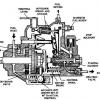
And if we zoom out we can see that the crankshaft has been trial fitted. This point of all this was we needed to measure the positions of the push rods so the manifolds were fitted to the cylinders in the right place. We also needed to get the piston rods the right length.
And here's a cylinder being machined. Our boring machine isn't bad but it doesn't have a live spindle which makes it a bit of a faff at times. If anyone has one with a live spindle looking for a new home for not much let me know and I'll be there tonight to pick it up. Note writing all over it so no one gets confused about which end is which.
Bored and faced. Just the sticky problem of the ports to go. And a few other things.
We did a job for a now defuct paper maker. Well, they were already defunct which was why we were doing the job. Because we were on site at the time we were allowed to have a trolley dash in what was left of their metals store. In the end we probably got a ton and a half of flat, round and hex bar as well as handy bits of pipe. Here is some of it carefully stored under the Goddess.
Non-ferrous cuttings bin. Turning down flanged bushes from cored bar causes a lot of these. We weigh them in occassionally in a pathetic attempt to make it look like we are saving money.
And this is the pile of steel and cast iron turnings generated over a weekend.
The final part of the diff jigsaw is the sprocket carriers. These hubs have the drive sprockets bolted to them. Take piece of stock bar and machine it until you have (i) one of these and (ii) a pile like the one above. Note shiny tappets.
The pile gets bigger and a lot less depressing.
Con rods with new big ends and little ends. New bolts for the big ends not yet made.
My old man does a lot of this. He likes writing lists so he can score things off. I tend to be a bit more slap dash in my approach to planning projects. There are a lot of white boards in the workshops.
Yet another long LDV drive to pick up some new (to us anyway) bending rolls. The poor LDV gets used a lot. Note yet another whiteboard in background.
And *drum roll* the finished differential fitted to the crankshaft. Important piece of progress this. If you understand that the sprocket carriers spin freely on the crankshaft you should be able to get how it works. One of the downsides of this design is that you can't lock it which was a lot handier then than it is now. The other disadvantage is that it is massively heavy and expected to spin at about 1400 RPM max.
One of the problems with the documenting what we do it that we are utterly piss poor at stopping to take photos so the record is a bit stilted to say the least. I've just been working through what few photos I've uploaded to Flickr over the past couple of years. This comes back to bite us time after time because we spend a lot of time wondering out loud "what did we do with the last one?" but because it was twenty years ago you can't remember. You end up scratching around a few photos searching for clues about what you did. Stuff pings into your head at three in the morning too. The point is that the next photo I uploaded is this one.
Oh. That's a bit of a jump. Cylinders finished and honed. Manifolds fitted, clad and the whole damn thing put together. Do you not think we could have got it together to take a few photos in all that time? No, apparently. Anyway. Here's a nearly finished Super Sentinel engine. We are in the process of setting the timing.
Closer on the cylinders and valves. Nothing polished or painted. Inlet valves at the top, exhaust at the bottom.
Compare this shot with the one when it arrived.
And we'll leave it at that today. Now the engine is somewhere near finished we need to start doing bits it needs to be a lorry.
-
 JimH got a reaction from djim in It is just so Super (Sentinel).
In the last episode the gears had returned fron Leek Gears and the bushes had been removed fro the crankshaft. Large chunks of bronze were then reduced to swarf to make new bushes. This pile here represents everything needed to make the differential for a Super. Ignore the black things. They are plastic supports for the drive shafts while things are being fitted up. Last episode I went on about shinking bushes in. This is a right old pain to do because it's helpful to have a supply of liquid nitrogen which is tricky or you need to heat things that you aren't entirely happy with heating. On top of that once you have fitted the bush you need to finish bore it.
However, on its white charger Modern Progress appears over the horizon in the shape of engineering adhesives. Now you fit the bush to the shaft and leave it slightly under sized so it slips into the housing. Then once you are happy with how everything fits you pop on some posh glue and wait for it to set. Brilliant. However, the world of engineering adhesives is a bit complicated and you need to know which ones to use and where. Spec sheets start to get quite long and weary. Still brilliant, though.
An almost complete water pump set up. Idler gear complete with eccentric, machined con rod, new pump ram (not yet machined to length) and bottle. There is a very important and complicated bit missing but we were still trying to talk to someone in Aus about one they were having cast. The pump ram has been made as big as we can get it into the body. This means we can get more water into the boiler.
About this point the milling machine broke. I believe that before we got it the thing had sat outside for a short time. I seems that water got into the quill bearing and it gave up the ghost. These are fiddly little buggers to work on but here it is returned to full health.
Close up of a tappet once it came out of the bead blaster. This one is one of the better ones. Not pretty. A little care and attention should return them to if not factory fresh at least a decent impression of it.
And the same tappets and lock plates fitted to the crank case. These are polished at the moment but they should be chemically blackened so they look right. Just another four to do.
And if we zoom out we can see that the crankshaft has been trial fitted. This point of all this was we needed to measure the positions of the push rods so the manifolds were fitted to the cylinders in the right place. We also needed to get the piston rods the right length.
And here's a cylinder being machined. Our boring machine isn't bad but it doesn't have a live spindle which makes it a bit of a faff at times. If anyone has one with a live spindle looking for a new home for not much let me know and I'll be there tonight to pick it up. Note writing all over it so no one gets confused about which end is which.
Bored and faced. Just the sticky problem of the ports to go. And a few other things.
We did a job for a now defuct paper maker. Well, they were already defunct which was why we were doing the job. Because we were on site at the time we were allowed to have a trolley dash in what was left of their metals store. In the end we probably got a ton and a half of flat, round and hex bar as well as handy bits of pipe. Here is some of it carefully stored under the Goddess.
Non-ferrous cuttings bin. Turning down flanged bushes from cored bar causes a lot of these. We weigh them in occassionally in a pathetic attempt to make it look like we are saving money.
And this is the pile of steel and cast iron turnings generated over a weekend.
The final part of the diff jigsaw is the sprocket carriers. These hubs have the drive sprockets bolted to them. Take piece of stock bar and machine it until you have (i) one of these and (ii) a pile like the one above. Note shiny tappets.
The pile gets bigger and a lot less depressing.
Con rods with new big ends and little ends. New bolts for the big ends not yet made.
My old man does a lot of this. He likes writing lists so he can score things off. I tend to be a bit more slap dash in my approach to planning projects. There are a lot of white boards in the workshops.
Yet another long LDV drive to pick up some new (to us anyway) bending rolls. The poor LDV gets used a lot. Note yet another whiteboard in background.
And *drum roll* the finished differential fitted to the crankshaft. Important piece of progress this. If you understand that the sprocket carriers spin freely on the crankshaft you should be able to get how it works. One of the downsides of this design is that you can't lock it which was a lot handier then than it is now. The other disadvantage is that it is massively heavy and expected to spin at about 1400 RPM max.
One of the problems with the documenting what we do it that we are utterly piss poor at stopping to take photos so the record is a bit stilted to say the least. I've just been working through what few photos I've uploaded to Flickr over the past couple of years. This comes back to bite us time after time because we spend a lot of time wondering out loud "what did we do with the last one?" but because it was twenty years ago you can't remember. You end up scratching around a few photos searching for clues about what you did. Stuff pings into your head at three in the morning too. The point is that the next photo I uploaded is this one.
Oh. That's a bit of a jump. Cylinders finished and honed. Manifolds fitted, clad and the whole damn thing put together. Do you not think we could have got it together to take a few photos in all that time? No, apparently. Anyway. Here's a nearly finished Super Sentinel engine. We are in the process of setting the timing.
Closer on the cylinders and valves. Nothing polished or painted. Inlet valves at the top, exhaust at the bottom.
Compare this shot with the one when it arrived.
And we'll leave it at that today. Now the engine is somewhere near finished we need to start doing bits it needs to be a lorry.
-
 JimH got a reaction from Rocket88 in It is just so Super (Sentinel).
A quick update. There are times when a lot gets done but there isn't a lot of visible progress.
However, this is reasonably visible. First fit of the front axle beam hanging on by the skin of its teeth. This is meant to be held in with a slice of 1/2" plate and 4 off 3/4" whit bolts. There will also be a 1" packing piece between the axle mount and the spring. This was to lift the chassis up to increase clearance when they converted them from solids to pneumatics. This will do for starters.
You should start to get an idea of how the front axle works. Badly, mainly.
Can't see the join. The bend is so it fits around the boiler. These were forged originally so they looked a little rough and ready. We've tried to replicate this. Once the paint is on it you wouldn't tell the difference.
So now the beam is in place we can go back to these bits which have lain on the floor for a few months while other things were done. A swivel. You see the big hole in the axle beam? That takes the pivot pin. Then the stub axles go through the big hole in the swivel. Ovbiously there are a few bronze bushes needed too.
The other thing that has been started is the cab. The footplate was cut and fitted a few weeks back so now we are happy with the curve on that all the other bits of the front apron copy it. This is the 1" angle that takes the bottom of the apron plate. Bending angle is a right pain in the arse and it takes a lot of heating and tweaking to get it right. Actually, bending angle is a piece of proverbial if you have bending rolls that can take angle but we don't so we have to freehand it.
A bit of 1" angle. Wow.
See the 12 foot radius on the front section? Important bit that. It's what makes a Super look like a Super.
The next bit is trickier. The angle sets the shape at the bottom of the cab but at the top where the roof is there is the ash bend. This was originally bent from a 3"x1" section of ash which was steamed and bent to shape. This wasn't very durable and if you look at period photographs (and a fair few current ones) you'll see ash bends bodged back together with plate, chewing gum and string. When we did the last one we fabricated the ash bend in steel which is somewhat more long lasting even if it is a bit of a pain to build.
There is a length of 1" box section at the top and the same at the bottom. There is then 3"x 1/8th flat section on the vertical faces. Tack it all together, make it look pretty and no one would ever tell the difference. Easy to say, takes a bit longer to do. It is made easier because you are trying to replicate the curves and angles of the footplate which means you have a handy, very stiff and just at the right height jig to work from. You should be able to make out the top and bottom box sections and the front vertical being tacked into place. I was actually in the process of taking it off at this point which is why there are almost no clamps on it. You never have enough clamps. Please be a tiny bit impressed with the shape. We're pretty pleased with that.
And the same from the other side. It got bigger than this after the picture was taken because it extends to the rear of the cab.
Check out the curves on that. There is a lot of welding, grinding and fettling to go before it looks plausible. Good start, though.
Things to think about while you are working. Express is falling out of favour, BTW.
We now have a Sentinel drawing for a van body which looks pretty good and shouldn't be too horrific to buy the wood for so it's definitely having a big box body on it. By the way - look at the top picture (photocopied out of a sales brochure which explains the flowery language) see the rail running around the roof of the cab? That's the ash bend. This picture isn't a perfect representation of what they actually made but it is a very good image to keep you on track while you try to work out what goes where.
Drawings from the archives. Most of the information is in there as long as you take everything with a pinch of salt.
This, for example is the rear hub for the pnuematic converstion. Make two of these and you've nearly got a back axle. Doddle. Ish.
Finally today the stiffening plate for the rear drawbar. A chunk of 1/4" plate which will be held in with 23 5/8" rivets. The bits of channel are what the water tank will hang from.
What's next:
Cab uprights to get bent
Front footplate to cut around steering box
Boiler to drop in
Front axle to get on with
Ash bend to finish
Wood cutting list to finalise
-
JimH got a reaction from mat_the_cat in It is just so Super (Sentinel).
A quick update. There are times when a lot gets done but there isn't a lot of visible progress.
However, this is reasonably visible. First fit of the front axle beam hanging on by the skin of its teeth. This is meant to be held in with a slice of 1/2" plate and 4 off 3/4" whit bolts. There will also be a 1" packing piece between the axle mount and the spring. This was to lift the chassis up to increase clearance when they converted them from solids to pneumatics. This will do for starters.
You should start to get an idea of how the front axle works. Badly, mainly.
Can't see the join. The bend is so it fits around the boiler. These were forged originally so they looked a little rough and ready. We've tried to replicate this. Once the paint is on it you wouldn't tell the difference.
So now the beam is in place we can go back to these bits which have lain on the floor for a few months while other things were done. A swivel. You see the big hole in the axle beam? That takes the pivot pin. Then the stub axles go through the big hole in the swivel. Ovbiously there are a few bronze bushes needed too.
The other thing that has been started is the cab. The footplate was cut and fitted a few weeks back so now we are happy with the curve on that all the other bits of the front apron copy it. This is the 1" angle that takes the bottom of the apron plate. Bending angle is a right pain in the arse and it takes a lot of heating and tweaking to get it right. Actually, bending angle is a piece of proverbial if you have bending rolls that can take angle but we don't so we have to freehand it.
A bit of 1" angle. Wow.
See the 12 foot radius on the front section? Important bit that. It's what makes a Super look like a Super.
The next bit is trickier. The angle sets the shape at the bottom of the cab but at the top where the roof is there is the ash bend. This was originally bent from a 3"x1" section of ash which was steamed and bent to shape. This wasn't very durable and if you look at period photographs (and a fair few current ones) you'll see ash bends bodged back together with plate, chewing gum and string. When we did the last one we fabricated the ash bend in steel which is somewhat more long lasting even if it is a bit of a pain to build.
There is a length of 1" box section at the top and the same at the bottom. There is then 3"x 1/8th flat section on the vertical faces. Tack it all together, make it look pretty and no one would ever tell the difference. Easy to say, takes a bit longer to do. It is made easier because you are trying to replicate the curves and angles of the footplate which means you have a handy, very stiff and just at the right height jig to work from. You should be able to make out the top and bottom box sections and the front vertical being tacked into place. I was actually in the process of taking it off at this point which is why there are almost no clamps on it. You never have enough clamps. Please be a tiny bit impressed with the shape. We're pretty pleased with that.
And the same from the other side. It got bigger than this after the picture was taken because it extends to the rear of the cab.
Check out the curves on that. There is a lot of welding, grinding and fettling to go before it looks plausible. Good start, though.
Things to think about while you are working. Express is falling out of favour, BTW.
We now have a Sentinel drawing for a van body which looks pretty good and shouldn't be too horrific to buy the wood for so it's definitely having a big box body on it. By the way - look at the top picture (photocopied out of a sales brochure which explains the flowery language) see the rail running around the roof of the cab? That's the ash bend. This picture isn't a perfect representation of what they actually made but it is a very good image to keep you on track while you try to work out what goes where.
Drawings from the archives. Most of the information is in there as long as you take everything with a pinch of salt.
This, for example is the rear hub for the pnuematic converstion. Make two of these and you've nearly got a back axle. Doddle. Ish.
Finally today the stiffening plate for the rear drawbar. A chunk of 1/4" plate which will be held in with 23 5/8" rivets. The bits of channel are what the water tank will hang from.
What's next:
Cab uprights to get bent
Front footplate to cut around steering box
Boiler to drop in
Front axle to get on with
Ash bend to finish
Wood cutting list to finalise
-
 JimH reacted to DodgeRover in What makes you grin? Antidote to grumpy thread
There's building work going on in one of the houses my grandad and his brothers built after the Second World War, just had a message to say when they lifted the kitchen floor they found a measuring tape and another tool sat on the dwarf wall, both a little rusty but still usable and marked made in Sheffield, I don't know whose they were but I would like to think they originally belonged to him, they have been put on one side for me.
-
 JimH got a reaction from cobblers in It is just so Super (Sentinel).
A quick update. There are times when a lot gets done but there isn't a lot of visible progress.
However, this is reasonably visible. First fit of the front axle beam hanging on by the skin of its teeth. This is meant to be held in with a slice of 1/2" plate and 4 off 3/4" whit bolts. There will also be a 1" packing piece between the axle mount and the spring. This was to lift the chassis up to increase clearance when they converted them from solids to pneumatics. This will do for starters.
You should start to get an idea of how the front axle works. Badly, mainly.
Can't see the join. The bend is so it fits around the boiler. These were forged originally so they looked a little rough and ready. We've tried to replicate this. Once the paint is on it you wouldn't tell the difference.
So now the beam is in place we can go back to these bits which have lain on the floor for a few months while other things were done. A swivel. You see the big hole in the axle beam? That takes the pivot pin. Then the stub axles go through the big hole in the swivel. Ovbiously there are a few bronze bushes needed too.
The other thing that has been started is the cab. The footplate was cut and fitted a few weeks back so now we are happy with the curve on that all the other bits of the front apron copy it. This is the 1" angle that takes the bottom of the apron plate. Bending angle is a right pain in the arse and it takes a lot of heating and tweaking to get it right. Actually, bending angle is a piece of proverbial if you have bending rolls that can take angle but we don't so we have to freehand it.
A bit of 1" angle. Wow.
See the 12 foot radius on the front section? Important bit that. It's what makes a Super look like a Super.
The next bit is trickier. The angle sets the shape at the bottom of the cab but at the top where the roof is there is the ash bend. This was originally bent from a 3"x1" section of ash which was steamed and bent to shape. This wasn't very durable and if you look at period photographs (and a fair few current ones) you'll see ash bends bodged back together with plate, chewing gum and string. When we did the last one we fabricated the ash bend in steel which is somewhat more long lasting even if it is a bit of a pain to build.
There is a length of 1" box section at the top and the same at the bottom. There is then 3"x 1/8th flat section on the vertical faces. Tack it all together, make it look pretty and no one would ever tell the difference. Easy to say, takes a bit longer to do. It is made easier because you are trying to replicate the curves and angles of the footplate which means you have a handy, very stiff and just at the right height jig to work from. You should be able to make out the top and bottom box sections and the front vertical being tacked into place. I was actually in the process of taking it off at this point which is why there are almost no clamps on it. You never have enough clamps. Please be a tiny bit impressed with the shape. We're pretty pleased with that.
And the same from the other side. It got bigger than this after the picture was taken because it extends to the rear of the cab.
Check out the curves on that. There is a lot of welding, grinding and fettling to go before it looks plausible. Good start, though.
Things to think about while you are working. Express is falling out of favour, BTW.
We now have a Sentinel drawing for a van body which looks pretty good and shouldn't be too horrific to buy the wood for so it's definitely having a big box body on it. By the way - look at the top picture (photocopied out of a sales brochure which explains the flowery language) see the rail running around the roof of the cab? That's the ash bend. This picture isn't a perfect representation of what they actually made but it is a very good image to keep you on track while you try to work out what goes where.
Drawings from the archives. Most of the information is in there as long as you take everything with a pinch of salt.
This, for example is the rear hub for the pnuematic converstion. Make two of these and you've nearly got a back axle. Doddle. Ish.
Finally today the stiffening plate for the rear drawbar. A chunk of 1/4" plate which will be held in with 23 5/8" rivets. The bits of channel are what the water tank will hang from.
What's next:
Cab uprights to get bent
Front footplate to cut around steering box
Boiler to drop in
Front axle to get on with
Ash bend to finish
Wood cutting list to finalise
-
 JimH got a reaction from MarvinsMom in It is just so Super (Sentinel).
A quick update. There are times when a lot gets done but there isn't a lot of visible progress.
However, this is reasonably visible. First fit of the front axle beam hanging on by the skin of its teeth. This is meant to be held in with a slice of 1/2" plate and 4 off 3/4" whit bolts. There will also be a 1" packing piece between the axle mount and the spring. This was to lift the chassis up to increase clearance when they converted them from solids to pneumatics. This will do for starters.
You should start to get an idea of how the front axle works. Badly, mainly.
Can't see the join. The bend is so it fits around the boiler. These were forged originally so they looked a little rough and ready. We've tried to replicate this. Once the paint is on it you wouldn't tell the difference.
So now the beam is in place we can go back to these bits which have lain on the floor for a few months while other things were done. A swivel. You see the big hole in the axle beam? That takes the pivot pin. Then the stub axles go through the big hole in the swivel. Ovbiously there are a few bronze bushes needed too.
The other thing that has been started is the cab. The footplate was cut and fitted a few weeks back so now we are happy with the curve on that all the other bits of the front apron copy it. This is the 1" angle that takes the bottom of the apron plate. Bending angle is a right pain in the arse and it takes a lot of heating and tweaking to get it right. Actually, bending angle is a piece of proverbial if you have bending rolls that can take angle but we don't so we have to freehand it.
A bit of 1" angle. Wow.
See the 12 foot radius on the front section? Important bit that. It's what makes a Super look like a Super.
The next bit is trickier. The angle sets the shape at the bottom of the cab but at the top where the roof is there is the ash bend. This was originally bent from a 3"x1" section of ash which was steamed and bent to shape. This wasn't very durable and if you look at period photographs (and a fair few current ones) you'll see ash bends bodged back together with plate, chewing gum and string. When we did the last one we fabricated the ash bend in steel which is somewhat more long lasting even if it is a bit of a pain to build.
There is a length of 1" box section at the top and the same at the bottom. There is then 3"x 1/8th flat section on the vertical faces. Tack it all together, make it look pretty and no one would ever tell the difference. Easy to say, takes a bit longer to do. It is made easier because you are trying to replicate the curves and angles of the footplate which means you have a handy, very stiff and just at the right height jig to work from. You should be able to make out the top and bottom box sections and the front vertical being tacked into place. I was actually in the process of taking it off at this point which is why there are almost no clamps on it. You never have enough clamps. Please be a tiny bit impressed with the shape. We're pretty pleased with that.
And the same from the other side. It got bigger than this after the picture was taken because it extends to the rear of the cab.
Check out the curves on that. There is a lot of welding, grinding and fettling to go before it looks plausible. Good start, though.
Things to think about while you are working. Express is falling out of favour, BTW.
We now have a Sentinel drawing for a van body which looks pretty good and shouldn't be too horrific to buy the wood for so it's definitely having a big box body on it. By the way - look at the top picture (photocopied out of a sales brochure which explains the flowery language) see the rail running around the roof of the cab? That's the ash bend. This picture isn't a perfect representation of what they actually made but it is a very good image to keep you on track while you try to work out what goes where.
Drawings from the archives. Most of the information is in there as long as you take everything with a pinch of salt.
This, for example is the rear hub for the pnuematic converstion. Make two of these and you've nearly got a back axle. Doddle. Ish.
Finally today the stiffening plate for the rear drawbar. A chunk of 1/4" plate which will be held in with 23 5/8" rivets. The bits of channel are what the water tank will hang from.
What's next:
Cab uprights to get bent
Front footplate to cut around steering box
Boiler to drop in
Front axle to get on with
Ash bend to finish
Wood cutting list to finalise
-
 JimH got a reaction from Asimo in It is just so Super (Sentinel).
A quick update. There are times when a lot gets done but there isn't a lot of visible progress.
However, this is reasonably visible. First fit of the front axle beam hanging on by the skin of its teeth. This is meant to be held in with a slice of 1/2" plate and 4 off 3/4" whit bolts. There will also be a 1" packing piece between the axle mount and the spring. This was to lift the chassis up to increase clearance when they converted them from solids to pneumatics. This will do for starters.
You should start to get an idea of how the front axle works. Badly, mainly.
Can't see the join. The bend is so it fits around the boiler. These were forged originally so they looked a little rough and ready. We've tried to replicate this. Once the paint is on it you wouldn't tell the difference.
So now the beam is in place we can go back to these bits which have lain on the floor for a few months while other things were done. A swivel. You see the big hole in the axle beam? That takes the pivot pin. Then the stub axles go through the big hole in the swivel. Ovbiously there are a few bronze bushes needed too.
The other thing that has been started is the cab. The footplate was cut and fitted a few weeks back so now we are happy with the curve on that all the other bits of the front apron copy it. This is the 1" angle that takes the bottom of the apron plate. Bending angle is a right pain in the arse and it takes a lot of heating and tweaking to get it right. Actually, bending angle is a piece of proverbial if you have bending rolls that can take angle but we don't so we have to freehand it.
A bit of 1" angle. Wow.
See the 12 foot radius on the front section? Important bit that. It's what makes a Super look like a Super.
The next bit is trickier. The angle sets the shape at the bottom of the cab but at the top where the roof is there is the ash bend. This was originally bent from a 3"x1" section of ash which was steamed and bent to shape. This wasn't very durable and if you look at period photographs (and a fair few current ones) you'll see ash bends bodged back together with plate, chewing gum and string. When we did the last one we fabricated the ash bend in steel which is somewhat more long lasting even if it is a bit of a pain to build.
There is a length of 1" box section at the top and the same at the bottom. There is then 3"x 1/8th flat section on the vertical faces. Tack it all together, make it look pretty and no one would ever tell the difference. Easy to say, takes a bit longer to do. It is made easier because you are trying to replicate the curves and angles of the footplate which means you have a handy, very stiff and just at the right height jig to work from. You should be able to make out the top and bottom box sections and the front vertical being tacked into place. I was actually in the process of taking it off at this point which is why there are almost no clamps on it. You never have enough clamps. Please be a tiny bit impressed with the shape. We're pretty pleased with that.
And the same from the other side. It got bigger than this after the picture was taken because it extends to the rear of the cab.
Check out the curves on that. There is a lot of welding, grinding and fettling to go before it looks plausible. Good start, though.
Things to think about while you are working. Express is falling out of favour, BTW.
We now have a Sentinel drawing for a van body which looks pretty good and shouldn't be too horrific to buy the wood for so it's definitely having a big box body on it. By the way - look at the top picture (photocopied out of a sales brochure which explains the flowery language) see the rail running around the roof of the cab? That's the ash bend. This picture isn't a perfect representation of what they actually made but it is a very good image to keep you on track while you try to work out what goes where.
Drawings from the archives. Most of the information is in there as long as you take everything with a pinch of salt.
This, for example is the rear hub for the pnuematic converstion. Make two of these and you've nearly got a back axle. Doddle. Ish.
Finally today the stiffening plate for the rear drawbar. A chunk of 1/4" plate which will be held in with 23 5/8" rivets. The bits of channel are what the water tank will hang from.
What's next:
Cab uprights to get bent
Front footplate to cut around steering box
Boiler to drop in
Front axle to get on with
Ash bend to finish
Wood cutting list to finalise
-
 JimH got a reaction from Quintus in The Jaywick Chevy
Before anyone says anything about Essex I implore them to watch The Joy of Essex by Jonathan Meades. There is a piss poor copy of it here https://youtu.be/kzNSOhGcQts
I don't really do telly but this is one of the best television programmes I have seen for a very long time. The final few minutes on the subject of planning are brilliant.
-
 JimH got a reaction from Dead_E23 in The Jaywick Chevy
Before anyone says anything about Essex I implore them to watch The Joy of Essex by Jonathan Meades. There is a piss poor copy of it here https://youtu.be/kzNSOhGcQts
I don't really do telly but this is one of the best television programmes I have seen for a very long time. The final few minutes on the subject of planning are brilliant.
-
 JimH got a reaction from somewhatfoolish in It is just so Super (Sentinel).
A quick update. There are times when a lot gets done but there isn't a lot of visible progress.
However, this is reasonably visible. First fit of the front axle beam hanging on by the skin of its teeth. This is meant to be held in with a slice of 1/2" plate and 4 off 3/4" whit bolts. There will also be a 1" packing piece between the axle mount and the spring. This was to lift the chassis up to increase clearance when they converted them from solids to pneumatics. This will do for starters.
You should start to get an idea of how the front axle works. Badly, mainly.
Can't see the join. The bend is so it fits around the boiler. These were forged originally so they looked a little rough and ready. We've tried to replicate this. Once the paint is on it you wouldn't tell the difference.
So now the beam is in place we can go back to these bits which have lain on the floor for a few months while other things were done. A swivel. You see the big hole in the axle beam? That takes the pivot pin. Then the stub axles go through the big hole in the swivel. Ovbiously there are a few bronze bushes needed too.
The other thing that has been started is the cab. The footplate was cut and fitted a few weeks back so now we are happy with the curve on that all the other bits of the front apron copy it. This is the 1" angle that takes the bottom of the apron plate. Bending angle is a right pain in the arse and it takes a lot of heating and tweaking to get it right. Actually, bending angle is a piece of proverbial if you have bending rolls that can take angle but we don't so we have to freehand it.
A bit of 1" angle. Wow.
See the 12 foot radius on the front section? Important bit that. It's what makes a Super look like a Super.
The next bit is trickier. The angle sets the shape at the bottom of the cab but at the top where the roof is there is the ash bend. This was originally bent from a 3"x1" section of ash which was steamed and bent to shape. This wasn't very durable and if you look at period photographs (and a fair few current ones) you'll see ash bends bodged back together with plate, chewing gum and string. When we did the last one we fabricated the ash bend in steel which is somewhat more long lasting even if it is a bit of a pain to build.
There is a length of 1" box section at the top and the same at the bottom. There is then 3"x 1/8th flat section on the vertical faces. Tack it all together, make it look pretty and no one would ever tell the difference. Easy to say, takes a bit longer to do. It is made easier because you are trying to replicate the curves and angles of the footplate which means you have a handy, very stiff and just at the right height jig to work from. You should be able to make out the top and bottom box sections and the front vertical being tacked into place. I was actually in the process of taking it off at this point which is why there are almost no clamps on it. You never have enough clamps. Please be a tiny bit impressed with the shape. We're pretty pleased with that.
And the same from the other side. It got bigger than this after the picture was taken because it extends to the rear of the cab.
Check out the curves on that. There is a lot of welding, grinding and fettling to go before it looks plausible. Good start, though.
Things to think about while you are working. Express is falling out of favour, BTW.
We now have a Sentinel drawing for a van body which looks pretty good and shouldn't be too horrific to buy the wood for so it's definitely having a big box body on it. By the way - look at the top picture (photocopied out of a sales brochure which explains the flowery language) see the rail running around the roof of the cab? That's the ash bend. This picture isn't a perfect representation of what they actually made but it is a very good image to keep you on track while you try to work out what goes where.
Drawings from the archives. Most of the information is in there as long as you take everything with a pinch of salt.
This, for example is the rear hub for the pnuematic converstion. Make two of these and you've nearly got a back axle. Doddle. Ish.
Finally today the stiffening plate for the rear drawbar. A chunk of 1/4" plate which will be held in with 23 5/8" rivets. The bits of channel are what the water tank will hang from.
What's next:
Cab uprights to get bent
Front footplate to cut around steering box
Boiler to drop in
Front axle to get on with
Ash bend to finish
Wood cutting list to finalise
-
 JimH got a reaction from Sigmund Fraud in It is just so Super (Sentinel).
A quick update. There are times when a lot gets done but there isn't a lot of visible progress.
However, this is reasonably visible. First fit of the front axle beam hanging on by the skin of its teeth. This is meant to be held in with a slice of 1/2" plate and 4 off 3/4" whit bolts. There will also be a 1" packing piece between the axle mount and the spring. This was to lift the chassis up to increase clearance when they converted them from solids to pneumatics. This will do for starters.
You should start to get an idea of how the front axle works. Badly, mainly.
Can't see the join. The bend is so it fits around the boiler. These were forged originally so they looked a little rough and ready. We've tried to replicate this. Once the paint is on it you wouldn't tell the difference.
So now the beam is in place we can go back to these bits which have lain on the floor for a few months while other things were done. A swivel. You see the big hole in the axle beam? That takes the pivot pin. Then the stub axles go through the big hole in the swivel. Ovbiously there are a few bronze bushes needed too.
The other thing that has been started is the cab. The footplate was cut and fitted a few weeks back so now we are happy with the curve on that all the other bits of the front apron copy it. This is the 1" angle that takes the bottom of the apron plate. Bending angle is a right pain in the arse and it takes a lot of heating and tweaking to get it right. Actually, bending angle is a piece of proverbial if you have bending rolls that can take angle but we don't so we have to freehand it.
A bit of 1" angle. Wow.
See the 12 foot radius on the front section? Important bit that. It's what makes a Super look like a Super.
The next bit is trickier. The angle sets the shape at the bottom of the cab but at the top where the roof is there is the ash bend. This was originally bent from a 3"x1" section of ash which was steamed and bent to shape. This wasn't very durable and if you look at period photographs (and a fair few current ones) you'll see ash bends bodged back together with plate, chewing gum and string. When we did the last one we fabricated the ash bend in steel which is somewhat more long lasting even if it is a bit of a pain to build.
There is a length of 1" box section at the top and the same at the bottom. There is then 3"x 1/8th flat section on the vertical faces. Tack it all together, make it look pretty and no one would ever tell the difference. Easy to say, takes a bit longer to do. It is made easier because you are trying to replicate the curves and angles of the footplate which means you have a handy, very stiff and just at the right height jig to work from. You should be able to make out the top and bottom box sections and the front vertical being tacked into place. I was actually in the process of taking it off at this point which is why there are almost no clamps on it. You never have enough clamps. Please be a tiny bit impressed with the shape. We're pretty pleased with that.
And the same from the other side. It got bigger than this after the picture was taken because it extends to the rear of the cab.
Check out the curves on that. There is a lot of welding, grinding and fettling to go before it looks plausible. Good start, though.
Things to think about while you are working. Express is falling out of favour, BTW.
We now have a Sentinel drawing for a van body which looks pretty good and shouldn't be too horrific to buy the wood for so it's definitely having a big box body on it. By the way - look at the top picture (photocopied out of a sales brochure which explains the flowery language) see the rail running around the roof of the cab? That's the ash bend. This picture isn't a perfect representation of what they actually made but it is a very good image to keep you on track while you try to work out what goes where.
Drawings from the archives. Most of the information is in there as long as you take everything with a pinch of salt.
This, for example is the rear hub for the pnuematic converstion. Make two of these and you've nearly got a back axle. Doddle. Ish.
Finally today the stiffening plate for the rear drawbar. A chunk of 1/4" plate which will be held in with 23 5/8" rivets. The bits of channel are what the water tank will hang from.
What's next:
Cab uprights to get bent
Front footplate to cut around steering box
Boiler to drop in
Front axle to get on with
Ash bend to finish
Wood cutting list to finalise
-
JimH got a reaction from djim in It is just so Super (Sentinel).
A quick update. There are times when a lot gets done but there isn't a lot of visible progress.
However, this is reasonably visible. First fit of the front axle beam hanging on by the skin of its teeth. This is meant to be held in with a slice of 1/2" plate and 4 off 3/4" whit bolts. There will also be a 1" packing piece between the axle mount and the spring. This was to lift the chassis up to increase clearance when they converted them from solids to pneumatics. This will do for starters.
You should start to get an idea of how the front axle works. Badly, mainly.
Can't see the join. The bend is so it fits around the boiler. These were forged originally so they looked a little rough and ready. We've tried to replicate this. Once the paint is on it you wouldn't tell the difference.
So now the beam is in place we can go back to these bits which have lain on the floor for a few months while other things were done. A swivel. You see the big hole in the axle beam? That takes the pivot pin. Then the stub axles go through the big hole in the swivel. Ovbiously there are a few bronze bushes needed too.
The other thing that has been started is the cab. The footplate was cut and fitted a few weeks back so now we are happy with the curve on that all the other bits of the front apron copy it. This is the 1" angle that takes the bottom of the apron plate. Bending angle is a right pain in the arse and it takes a lot of heating and tweaking to get it right. Actually, bending angle is a piece of proverbial if you have bending rolls that can take angle but we don't so we have to freehand it.
A bit of 1" angle. Wow.
See the 12 foot radius on the front section? Important bit that. It's what makes a Super look like a Super.
The next bit is trickier. The angle sets the shape at the bottom of the cab but at the top where the roof is there is the ash bend. This was originally bent from a 3"x1" section of ash which was steamed and bent to shape. This wasn't very durable and if you look at period photographs (and a fair few current ones) you'll see ash bends bodged back together with plate, chewing gum and string. When we did the last one we fabricated the ash bend in steel which is somewhat more long lasting even if it is a bit of a pain to build.
There is a length of 1" box section at the top and the same at the bottom. There is then 3"x 1/8th flat section on the vertical faces. Tack it all together, make it look pretty and no one would ever tell the difference. Easy to say, takes a bit longer to do. It is made easier because you are trying to replicate the curves and angles of the footplate which means you have a handy, very stiff and just at the right height jig to work from. You should be able to make out the top and bottom box sections and the front vertical being tacked into place. I was actually in the process of taking it off at this point which is why there are almost no clamps on it. You never have enough clamps. Please be a tiny bit impressed with the shape. We're pretty pleased with that.
And the same from the other side. It got bigger than this after the picture was taken because it extends to the rear of the cab.
Check out the curves on that. There is a lot of welding, grinding and fettling to go before it looks plausible. Good start, though.
Things to think about while you are working. Express is falling out of favour, BTW.
We now have a Sentinel drawing for a van body which looks pretty good and shouldn't be too horrific to buy the wood for so it's definitely having a big box body on it. By the way - look at the top picture (photocopied out of a sales brochure which explains the flowery language) see the rail running around the roof of the cab? That's the ash bend. This picture isn't a perfect representation of what they actually made but it is a very good image to keep you on track while you try to work out what goes where.
Drawings from the archives. Most of the information is in there as long as you take everything with a pinch of salt.
This, for example is the rear hub for the pnuematic converstion. Make two of these and you've nearly got a back axle. Doddle. Ish.
Finally today the stiffening plate for the rear drawbar. A chunk of 1/4" plate which will be held in with 23 5/8" rivets. The bits of channel are what the water tank will hang from.
What's next:
Cab uprights to get bent
Front footplate to cut around steering box
Boiler to drop in
Front axle to get on with
Ash bend to finish
Wood cutting list to finalise